INDUCTION MOTORS
|
Induction motors use electromagnetic forces to create motion relative to a conducting surface. In a rotary arrangement, the forces turn a motor such as used with the electric car, water pumps, and electric fans. In a linear arrangement, the forces can propel a train along an aluminum strip (third rail) without touching the strip.
For both rotary induction motors and linear induction motors, the technology is far from meeting its potential. In particular, Homeland Technologies is advancing technology on self-assembling magnet cores that provides significant advantages in reducing costs and decreasing weights of these motors. The induction motor makes high-speed switching smooth and effective ... see slideshow on bottom of page. |
|
Open-Sided Coil Short Stators
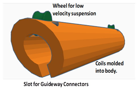
Illustrated (right) is the open-sided stator part of patent-pending linear motor technology; the armature is the cable/pipe runs along, providing non-contact propulsion. Magnetic forces both pull the stator along the cable and keep the cable centered in the stator. The wheels are for low-velocity transit when aerodynamic forces are inadequate to fully support the weight of the vehicle attached to the open-sided stator. It does work ... see above slideshow.
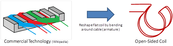
Molded into the body of the open-sided stator are open-sided coils. Illustrated (below) is an open-sided coil. Basically, the flat coils of a traditional linear motor (i.e., commercial technology) are bend around the armature of choice (e.g. a cable). Propulsion and suspension forces are transformed to propulsion and magnetic-bearing forces which provide both propulsion and guidance. The open-sided coil has a slot through which armature connectors may pass.
Illustrated (right) is the open-sided stator part of patent-pending linear motor technology; the armature is the cable/pipe runs along, providing non-contact propulsion. Magnetic forces both pull the stator along the cable and keep the cable centered in the stator. The wheels are for low-velocity transit when aerodynamic forces are inadequate to fully support the weight of the vehicle attached to the open-sided stator. It does work ... see above slideshow.
Molded into the body of the open-sided stator are open-sided coils. Illustrated (below) is an open-sided coil. Basically, the flat coils of a traditional linear motor (i.e., commercial technology) are bend around the armature of choice (e.g. a cable). Propulsion and suspension forces are transformed to propulsion and magnetic-bearing forces which provide both propulsion and guidance. The open-sided coil has a slot through which armature connectors may pass.
Self-assembly core technology uses a molding processes to form the core and stator body around coils positioned in the mold. The technology promises to realize major reductions in weight for the propulsion means. For Terreplane the armature is also the guideway, eliminating the weight of the motor's armature from that of the vehicle-chassis assembly. The needed magnetic forces for this system are estimated to be 1/20th the magnetic forces needed for suspension and propulsion for maglev trains (the needed for superconductivity and all its engineering and maintenance burdens are eliminated). For Terreplane applications, patents are pending on open-sided electromagnet devices pull and guide the vehicles along the guideway cables without contact or noise. The below link provides details.

|
Self-Assembling Electromagnet Cores
For the fabrication of a linear motor of the type of the above Wikipedia illustration (as part of Terreplane R&D), the following was noted: a) the preparation and welding of the rectangular core was cumbersome, b) the coils were difficult to place and hold tightly in the slots, and c) wire insulation was damaged in forcing the coils into the slots. Also, the core orientation was vertical rather than at the desired pitch/slant. These observations and difficulties led to the development of self-assembling core technology, where the core is molded around the coils. To right .. slide show on induction motors. |
|
Self-assembling core technology produces a core comprised of particles (e.g. ferromagnetic) bound together (and to coils) with a thermoset polymer. The resulting product is substantially free of air gaps and of complex/optimal geometries including an elimination of sections of the extended core that do not contribute (significantly) to the desired flux of the magnetic field. When the coils are in a short stator, a single molding process can form the cores and body of the short stator resulting in a product that is more robust, lighter weight, and lower cost (easier to manufacture) ... hence the statement that induction motor technology had barely started to realize its potential.
Short-Stator Chassis
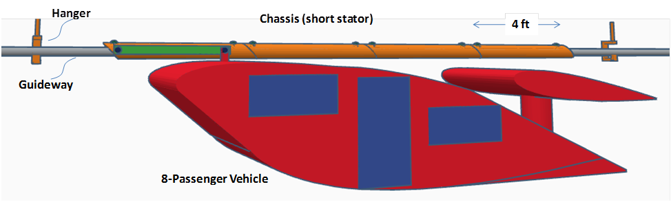
When the open-sided short stator travels along a cable armature, that stator can become the chassis of a Terreplane vehicle. The vehicle is attached to that chassis with an arm. At sufficient speed and with proper aerodynamic shape, the weight of the vehicle (and arm and chassis) is supported by the aerodynamic forces. Shock absorbers (dampers) and flaps can isolate disturbances from the cable armature guideway in a manner where the primary force on the guideway is a pulling (longitudinal) force. This combination creates a synergy where an inexpensive (1/5th the cost of alternatives) cable guideway is not only adequate, but also, provides a bump-free self-straightening guideway that is ideal for travel speeds of 90, 180, 360, and even 720 mph. The below figure illustrates this combination.
When the open-sided short stator travels along a cable armature, that stator can become the chassis of a Terreplane vehicle. The vehicle is attached to that chassis with an arm. At sufficient speed and with proper aerodynamic shape, the weight of the vehicle (and arm and chassis) is supported by the aerodynamic forces. Shock absorbers (dampers) and flaps can isolate disturbances from the cable armature guideway in a manner where the primary force on the guideway is a pulling (longitudinal) force. This combination creates a synergy where an inexpensive (1/5th the cost of alternatives) cable guideway is not only adequate, but also, provides a bump-free self-straightening guideway that is ideal for travel speeds of 90, 180, 360, and even 720 mph. The below figure illustrates this combination.
|
High-Speed, Vehicle-Controlled Guideway Switching (a slideshow)
High-speed vehicle-controlled switching is important for both capacity considerations and the offer of non-stop service. When combined with inexpensive guideways ($0.5M per mile for additional pairs), the Terreplane System is able to perform at levels rarely imagined possible. |
|