AVIATION'S NEW ERA
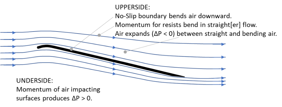
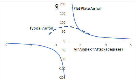
Figure 1. Science of flight. Figure 2. L/D of flat plate airfoil versus typical wing.
Chapter 2. The Science of Flight
Aerodynamic forces create aerodynamic lift by producing increased pressure on the lower surfaces of aircraft and decreased pressure on the upper surfaces. The pressure time area produced lift force with the vertical component being lift. This is an example of Newton’s first law which identifies an object will not change its motion unless a force acts on it. This science is the foundation of aerodynamic lift.
More specifically, an aircraft flying at a steady state (constant speed, direction, and altitude) has zero net forces acting on it. Applying a steady state vertical force balance on the control volume defined by the aircrafts surface results in the equation 1:
0 = mg + ʃ [nv P dS] (1)
Where m is the mass of the aircraft, g is gravitational acceleration, P is pressure, S is area, nv is the vertical component of the unit vector normal to the surface, and ʃ identifies a surface integral. The surface integral is the integral of the pressure over the surface of the aircraft acting the in vertical direction, therefore providing the net force of pressure on the aircraft for the creation of lift.
The two terms of Equation 1 are equal and opposite force terms leading to zero net force in steady-state flight. “mg” is the weight of the aircraft. Pressure action on a surface creates a force normal to that surface; the vertical component of that vector is lift and the horizontal component is drag. Equation 1 is the balance of vertical forces; it does not include the drag and thrust terms of a force balance which act horizontally.
Figure 1 illustrates an example aerodynamic surface. Aerodynamic lift is created by oncoming air’s momentum impacting the lower surfaces and the expansion of air above upper surfaces. As illustrated by Figure 1, a no-slip constraint causes air next to an upper surface to follow the surface while adjacent air’s momentum pulls and expands away from that surface, creating lower pressure.
For any point on the thin surface, the lift is cos(θ) ΔP dS, the drag is sin(θ) ΔP dS, and the lift- drag ratio (“L/D”) may be defined as cot(θ) where: θ° is air’s angle of attack, ΔP is the pressure difference between the top and bottom of the thin plate, dS is a surface’s area, and form drag is the total drag when neglecting shear drag. For a flat plate, θ° is constant, and the limit of a large or thin flat plate (negligible edge surface area) is,
L/D = 57/ θ° (at low θ°, less than 15 degrees, θ in degrees) (2)
The lift- drag ratio (“L/D”) is a measure of flight efficiency. The best jet aircraft have L/D between 15 and 21, and typical vertical takeoff aircraft have L/D < 5. Equation 2 identifies L/D of 114 < L/D < 57 for 0.5° < θ° < 1.0° for an ideal flat plate airfoil, which suggests that a more than threefold increase in fuel economy is possible.
Figure 2 provides a plot of L/D versus air’s angle for the Equation 2 estimate for a flat plate airfoil and for a typical airfoil. At low positive air angles of attack, the flat plate airfoil can exceed the performance of a typical airfoil.
Equation 2 takes into account neither shear drag of surfaces nor the form drag of front edges of an airfoil. These corrections are covered in Chapter 4. When well designed, the corrections start at less than 10%.
The traditional airfoil provides high stability during flight and produces a decent L/D ratio for maintaining air travel. However, significant increases in efficiency are possible with the flat plate airfoil.
Interpreting the Science – If the objective of an aircraft is an L/D of 57:1, which is >3X contemporary airliners, Equation 2 identifies that any surfaces having an air angle of attack >1° will detract from performance. The conclusion is that to attain this high value of L/D, an abundance of substantially horizontal angle of attack (e.g., between 0.2° and 0.8°) is necessary.
In practice, higher pressures generated by steeper pitch angles can expand to flatter surfaces; this topic will be considered in greater detail in Chapter 8. But the need for the pressure to manifest to lift on these substantially horizontal surfaces for high efficiency is definitive in the science.
While discussions tend to be easier in terms of the positive pressures on the underside of aircraft, analogous science and conclusions apply to upper surfaces. To a first approximation, a thin airfoil of uniform thickness would generate lift from decreased pressure on the upper surface comparable to that generated on lower surfaces.

